WiFi
Wi-Fi instructions
Wi-Fi function list
- Compatible with IEEE802.11 b/g/n 2.4GHz standard
- Support HT20
- Support 802.11N MCS0-7
- Support STA, AP, and Direct Modes
- Support Concurrent AP+STA
- Supports encryption methods such as WPA, WPA2 and WPA3
- Support AMPDU, QoS
- Supports DTIM low-power sleep in Station mode
Wi-Fi callback event description
static void app_demo_sta_rw_event_func(void *new_evt)
{
    rw_evt_type notice_event = *((rw_evt_type *)new_evt);

    switch(notice_event){
        case RW_EVT_STA_CONNECTED:
            bk_printf("conmected AP\r\n");
            break;

        case RW_EVT_STA_GOT_IP:
            bk_printf("got ip success\r\n");
            break;

        case RW_EVT_STA_DISCONNECTED:
        case RW_EVT_STA_BEACON_LOSE:
            bk_printf("wifi had disconnected\r\n");
            break;

        case RW_EVT_STA_NO_AP_FOUND:
        case RW_EVT_STA_PASSWORD_WRONG:
        case RW_EVT_STA_ASSOC_FULL:
        case RW_EVT_STA_CONNECT_FAILED:
            bk_printf("wifi connect failed\r\n");
            break;

        case RW_EVT_AP_CONNECTED:
            bk_printf("a station had connected\r\n");
            break;
        case RW_EVT_AP_DISCONNECTED:
            bk_printf("a station had disconnected\r\n");
            break;
        case RW_EVT_AP_CONNECT_FAILED:
            bk_printf("a station connect failed\r\n");
            break;
        default:
            break;
    }
}

bk_wlan_status_register_cb(app_demo_sta_rw_event_func)
As in the above example, wifi initialization requires registering an event callback.
- RW_EVT_STA_CONNECTED
The wifi connection success event only means that the wifi four-way handshake is successful. It also needs to start the DHCP service to obtain an IP address or use a static IP address. Therefore, the user cannot start network operations at this event.
- RW_EVT_STA_GOT_IP
STA has successfully connected and obtained the IP address through DHCP. After receiving this event, the user can perform network interface operations.
- RW_EVT_STA_DISCONNECTED
- RW_EVT_STA_BEACON_LOSE
STA and AP disconnect event. After receiving this event, it is generally necessary to notify the client application written based on sockets to close the socket. If this event is not what the user expects, the reconnection process can be started.
- RW_EVT_STA_NO_AP_FOUND
- RW_EVT_STA_PASSWORD_WRONG
- RW_EVT_STA_ASSOC_FULL
- RW_EVT_STA_CONNECT_FAILED
These events are notifications of connection failure. Users can obtain the reason for the connection failure and then reconnect.
Wi-Fi Cli Command Guide
To facilitate customers to quickly understand the SDK and develop and debug it, the SDK integrates some basic Wi-Fi operation instructions.
beken378\func\wlan_ui\wlan_cli.c
Introduction to CLI command
The Wi-Fi-related CLI commands supported by the SDK are as follows:
| Command | Param | Description |
|---|---|---|
| sta: sta [ssid] [password] | param1: ssid | target router |
| param2: password | Target router password | |
| ap: ap ssid [password] | param1: ssid | Custom hotspot name |
| param2: password | Custom hotspot password | |
| scan: scan | none | Scan all nearby hotspots |
| ping: ping [ip] [count] | param1:ip | Target host IP address |
| param2: count | Number of Ping packets | |
| wifistate: wifistate – show STA/AP state | none | Display current Station/SoftAP status |
| ifconfig: ip – show STA/AP ip | none | Display current Station network connection parameters |
| stopintf: stop {sta|ap} intfacename | 1:sta 0:ap | Stop the current Station/SoftAP |
| iperf: iperf [-s|-c|-stop] | -s | DUT as Server |
| -c -u | DUT as Client, -u means UDP | |
| -stop | stop |
Bluetooth Low Energy (BLE)
Overview
The Bluetooth module provides users with interface functions such as scanning, connection, broadcast, and data transmission for short-distance communication. Bluetooth is composed of one or more task execution bodies and relies on a Bluetooth interrupt driver to run. Bluetooth has multiple events and callbacks, which constitute feedback called by the user.
Generally speaking, the actively connected device is called central/master/client, and the connected device is called peripheral/slaver/server. Once the connection relationship between the two ends is determined, it will not change.
API call Precautions
Most APIs have callback parameters, and you should wait for the callback execution to complete before proceeding to the next step. The processing of callback and event callback should not have blocking operations, and tasks that are too complex and time-consuming should not be processed. The call stack of callback cannot be too deep.
Important:
You should try your best to avoid the Bluetooth task being blocked, otherwise, abnormal phenomena such as disconnection, failure to scan, and failure to connect will occur.
Common usage scenarios
Slave mode, create an ATT database for peer browsing
BLE uses the ATT database as a double-ended operating entity, and all read-and-write notifications and other operations are performed on the ATT database. To build a standard-compliant database, you need to understand the concepts of services, characteristics, and UUIDs.
- Record: A piece of data in the database is called a record, which consists of a handle, type, and value.
- Services: Each ATT database has one or more services, such as HID, and HeartRate.
- Features: Each service contains one or more features. For example, HID includes a HID map and a HID report. The former is a key mapping table and the latter is a key reporting table. The specific operation is to first read the HID map and then parse the HID report according to the map. Know the specific value of the button.
- UUID: The above all exist in the form of records in the ATT database. To know these special records, the UUID value specified by the Bluetooth standard must be used to assign the type of the record. For example, DECL_PRIMARY_SERVICE_128 (0x2800) indicates that this record is a service declaration.
The following are specific examples
// Service Statement
#define BK_ATT_DECL_PRIMARY_SERVICE_128     {0x00,0x28,0x0,0x0,0x0,0x0,0x0,0x0,0x0,0x0,0x0,0x0,0x0,0x0,0x0,0x0}

// Feature declaration
#define BK_ATT_DECL_CHARACTERISTIC_128      {0x03,0x28,0x0,0x0,0x0,0x0,0x0,0x0,0x0,0x0,0x0,0x0,0x0,0x0,0x0,0x0}

// Feature client configuration declaration. This is a special UUID, indicating that this record is used to configure the described characteristics, generally including notify and indicate.
#define BK_ATT_DESC_CLIENT_CHAR_CFG_128     {0x02,0x29,0x0,0x0,0x0,0x0,0x0,0x0,0x0,0x0,0x0,0x0,0x0,0x0,0x0,0x0}
#define WRITE_REQ_CHARACTERISTIC_128        {0x01,0xFF,0x0,0x0,0x0,0x0,0x0,0x0,0x0,0x0,0x0,0x0,0x0,0x0,0x0,0x0}
#define INDICATE_CHARACTERISTIC_128         {0x02,0xFF,0x0,0x0,0x0,0x0,0x0,0x0,0x0,0x0,0x0,0x0,0x0,0x0,0x0,0x0}
#define NOTIFY_CHARACTERISTIC_128           {0x03,0xFF,0x0,0x0,0x0,0x0,0x0,0x0,0x0,0x0,0x0,0x0,0x0,0x0,0x0,0x0}

// Service UUID
static const uint8_t test_svc_uuid[16] = {0xFF,0xFF,0,0,0x34,0x56,0,0,0,0,0x28,0x37,0,0,0,0};

// Database index:
enum
{
        TEST_IDX_SVC,
        TEST_IDX_FF01_VAL_CHAR,
        TEST_IDX_FF01_VAL_VALUE,
        TEST_IDX_FF02_VAL_CHAR,
        TEST_IDX_FF02_VAL_VALUE,
        TEST_IDX_FF02_VAL_IND_CFG,
        TEST_IDX_FF03_VAL_CHAR,
        TEST_IDX_FF03_VAL_VALUE,
        TEST_IDX_FF03_VAL_NTF_CFG,
        TEST_IDX_NB,
};

// database
bk_attm_desc_t test_att_db[TEST_IDX_NB] =
{
        //  Service Declaration
        [TEST_IDX_SVC]              = {BK_ATT_DECL_PRIMARY_SERVICE_128, PROP(RD), 0},

        //  Level Characteristic Declaration
        [TEST_IDX_FF01_VAL_CHAR]    = {BK_ATT_DECL_CHARACTERISTIC_128,  PROP(RD), 0},
        //  Level Characteristic Value
        [TEST_IDX_FF01_VAL_VALUE]   = {WRITE_REQ_CHARACTERISTIC_128,    PROP(WR)|ATT_UUID(128), 128|OPT(NO_OFFSET)},

        [TEST_IDX_FF02_VAL_CHAR]    = {BK_ATT_DECL_CHARACTERISTIC_128,  PROP(RD), 0},
        //  Level Characteristic Value
        [TEST_IDX_FF02_VAL_VALUE]   = {INDICATE_CHARACTERISTIC_128,     PROP(I), 128|OPT(NO_OFFSET)},
        //  Level Characteristic - Client Characteristic Configuration Descriptor
        [TEST_IDX_FF02_VAL_IND_CFG] = {BK_ATT_DESC_CLIENT_CHAR_CFG_128, PROP(RD)|PROP(WR),OPT(NO_OFFSET)},

        [TEST_IDX_FF03_VAL_CHAR]    = {BK_ATT_DECL_CHARACTERISTIC_128,  PROP(RD), 0},
        //  Level Characteristic Value
        [TEST_IDX_FF03_VAL_VALUE]   = {NOTIFY_CHARACTERISTIC_128,       PROP(N), 128|OPT(NO_OFFSET)},
        //  Level Characteristic - Client Characteristic Configuration Descriptor
        [TEST_IDX_FF03_VAL_NTF_CFG] = {BK_ATT_DESC_CLIENT_CHAR_CFG_128, PROP(RD)|PROP(WR), OPT(NO_OFFSET)},
};

void ble_notice_cb(ble_notice_t notice, void *param)
{
        switch (notice) {
                case BLE_5_STACK_OK:         // Protocol stack initialization successful
                case BLE_5_WRITE_EVENT:      // Write events
                case BLE_5_READ_EVENT:       // Read event
                case BLE_5_TX_DONE:         // notify/indicate sends success event
                case BLE_5_REPORT_ADV:       // scan result reporting event
                case BLE_5_MTU_CHANGE:       // mtu change event
                case BLE_5_CONNECT_EVENT:    // slave mode connection event
                case BLE_5_DISCONNECT_EVENT: // slave disconnect event
                case BLE_5_CREATE_DB:        // Service creation completion event
                        break;
        }
}

struct bk_ble_db_cfg ble_db_cfg;
ble_db_cfg.att_db = (ble_attm_desc_t *)test_service_db;
ble_db_cfg.att_db_nb = TEST_IDX_NB;

// server handle,It should be different every time you create a database.
ble_db_cfg.prf_task_id = g_test_prf_task_id;
ble_db_cfg.start_hdl = 0;

// The type of UUID of the service record, here it is 128bit
ble_db_cfg.svc_perm = BK_BLE_PERM_SET(SVC_UUID_LEN, UUID_128);

// Copy service specific values
os_memcpy(&(ble_db_cfg.uuid[0]), &test_svc_uuid, 16);

// Register event callback
ble_set_notice_cb(ble_at_notice_cb);

// Create database
bk_ble_create_db(&ble_db_cfg);
At this point we get a service with a UUID of {0xFF,0xFF,0,0,0×34,0x56,0,0,0,0,0×28,0x37,0,0,0,0}, which contains a UUID of { Characteristics of 0x01,0xFF,0x0,0x0,0x0,0x0,0x0,0x0,0x0,0x0,0x0,0x0,0x0,0x0,0x0,0x0}, which have to write permission; Characteristics whose UUID is {0x02,0xFF}, has the indicated attribute; UUID is characteristic of {0x03,0xFF}, has the notify attribute;
Important:
1. Server UUID len can be configured through ble_db_cfg.svc_perm = BK_BLE_PERM_SET(SVC_UUID_LEN, UUID_128). UUID_LEN has UUID_16 and UUID_128.
2. Characteristic UUID len is the same as adding ATT_UUID(uuid_len) to the corresponding Characteristic info variable in the database db. uuid_len is generally 16 or 128.
3. When the event callback function ble_notice_cb receives the BLE_5_CREATE_DB event, the service is successfully created. If you need to create multiple services, you can continue to create other services after this event, in which ble_db_cfg.prf_task_id needs to be increased by 1;
Turn on the broadcast in Slave Mode
After setting up the service, you need to turn on broadcasting so that the peer can scan.
void ble_cmd_cb(ble_cmd_t cmd, ble_cmd_param_t *param)
{
        bk_printf("cmd:%d idx:%d status:%d\r\n", cmd, param->cmd_idx, param->status);
}

chnl_map = 7;
adv_intv_min = 0x120; // min
adv_intv_max = 0x160; // max

// Get the currently idle active index, used to start broadcasting
actv_idx = app_ble_get_idle_actv_idx_handle();
if (actv_idx != UNKNOW_ACT_IDX) {
        bk_ble_create_advertising(actv_idx,chnl_map,adv_intv_min,adv_intv_max, ble_cmd_cb);
}

// In ble_at_cmd_cb, wait for the BLE_CREATE_ADV event
...
//

// Bluetooth broadcast data, please refer to ble standard format
const uint8_t adv_data[] = {0x0A, 0x09, 0x37 0x32, 0x33, 0x31, 0x4e, 0x5f, 0x42, 0x4c, 0x45};
bk_ble_set_adv_data(actv_idx, adv_data, sizeof(adv_data), ble_cmd_cb);

// In ble_at_cmd_cb, wait for the BLE_SET_ADV_DATA event
...
//

// Scan response data, please refer to ble standard format
const uint8_t adv_data[] = {0x0A, 0x09, 0x37 0x32, 0x33, 0x31, 0x4e, 0x5f, 0x42, 0x4c, 0x45};
bk_ble_set_ext_adv_data(actv_idx, adv_data, sizeof(adv_data), ble_cmd_cb);


// In ble_at_cmd_cb, wait for the BLE_SET_RSP_DATA event
...
//

// Turn on broadcast
bk_ble_start_advertising(actv_idx, 0, ble_cmd_cb);

// In ble_at_cmd_cb, wait for the BLE_START_ADV event to complete the broadcast.
...
// in ble_notice_cb
Enable scanning in the Master Mode
actv_idx = app_ble_get_idle_actv_idx_handle();
bk_ble_create_scaning(actv_idx, ble_cmd_cb);

// In ble_at_cmd_cb, wait for BLE_CREATE_SCAN
...
//

scan_intv=100;
scan_wd=30;
bk_ble_start_scaning(actv_idx,scan_intv, scan_wd,ble_cmd_cb);

// In ble_at_cmd_cb, wait for BLE_START_SCAN
...
//

// Obtain the scan result broadcast data in the BLE_5_REPORT_ADV event in ble_notice_cb_t
Establish Connection in Master Mode
// Get the currently idle active index for establishing a connection
con_idx = bk_ble_get_idle_conn_idx_handle();
con_interval = 0x40;     //interval
con_latency = 0;
sup_to = 0x200;          //supervision timeout
bk_ble_create_init(con_idx, con_interval, con_latency,sup_to,ble_cmd_cb);

// In ble_at_cmd_cb, wait for BLE_INIT_CREATE
...
//

// Set the peer address type. Mismatch will cause the connection to fail.
struct bd_addr bdaddr;
uint8_t mac[6]={0xc8,0x47,0x8c,0x11,0x22,0x33};
memcpy(bdaddr.addr,mac,6);
addr_type = ADDR_PUBLIC;
bk_ble_init_set_connect_dev_addr(actv_idx,&bdaddr,addr_type);


bk_ble_init_start_conn(con_idx, ble_cmd_cb)

// In ble_at_cmd_cb, wait for BLE_INIT_START_CONN
...
// Waiting for BLE_5_INIT_CONNECT_EVENT in ble_notice_cb, the connection to the slave is successful
Introduction to CLI Commands
Slave Mode
- Start/stop general broadcast
Approach one:
Turn on broadcast
ble active
ble create_adv
ble set_adv_data
ble set_adv_data 0
ble set_rsp_data 0
ble start_adv 0

Stop broadcasting
ble stop_adv 0

Approach Two:
Turn off broadcast
ble active
ble init_adv

Stop broadcasting
ble deinit_adv
- Enable/stop expanding general broadcast
Turn on expanded broadcast
ble active
ble create_ext_adv 1 0
ble set_ext_adv_data 0
ble set_ext_rsp_data 0
ble start_adv 0

Stop expanding broadcast
ble stop_adv 0
- After being connected by the master, notify/indicate sends data
notify send
ble notify 0

indicate send
ble indicate 0
- After being connected by the master, update the connection parameters
ble update_conn 0
- After being connected by the master, it actively disconnects
ble dis_conn 0
- Start SMP encrypted pairing
//legacy pairing
ble smp_init 0

// secure connection pairiing
ble smp_init 1

//ble send security request
ble sec_req 0
Master Mode
- Start/stop scanning
# Approach one:
# Start scanning
ble active
ble create_scan
ble start_scan 0

# Stop Scanning
ble stop_scan 0

# Approach two:
# Start scanning
ble active
ble init_scan

# Stop scanning
ble deinit_scan
- master initiates connection
ble con_create

// 4900428c47c8 represents the slave mac, little endian, the first 0 represents the address type, 0: Public BD address 1: Random BD Address, usually 0)
ble con_start 4900428c47c8 0 0
- Read and write operations after a successful connection
//17 needs to be changed to a handler corresponding to the writable attribute of the slave service
ble con_write 17 0

//17 needs to be changed to a handler corresponding to the readable attributes of the slave service
ble con_read 17 0
- After the connection is successful, it will be automatically disconnected.
ble con_dis 0
Peripherals and Drivers
PWM
BK7238 has six 32-bit PWM channels, labeled PWM0~5 (supports timer mode). Each PWM channel has three modes: timer mode, PWM mode, and capture mode. Each pattern per channel is multiplexed with a 32-bit count.
The main functions of the PWM module are as follows:
- The counter increases in one direction and automatically continues counting from 0 when it overflows to the maximum value.
- Each channel can be enabled individually and the mode of each channel can be configured individually.
- Ability to count continuously between two rising edges, two falling edges, or both edges in capture mode
- Configurable PWM period and duty cycle for each PWM channel
- Real-time count values can be read in timer mode.
PWM Mode
//Turn on PWM
channel=1;                     // PWM1
frequency=(260000/1000)*2000;  // 2 KHz

duty_cycle1= frequency/4;      // High level duty cycle 1/4
duty_cycle12= 0;
duty_cycle13= 0;
bk_pwm_initialize(channel, (260000/1000)*frequency, duty_cycle1,duty_cycle12,duty_cycle13);
bk_pwm_start(channel1);

// Update PWM parameters
frequency=(260000/1000)*1000;  // 1 KHz
duty_cycle1= frequency/2;      // High level duty cycle 1/2
bk_pwm_update_param(channel, frequency, duty_cycle1);
Capture Mode
#define PWM_CAP_POS_MODE            (0x04)  // Capture (pos -> pos)
#define PWM_CAP_NEG_MODE            (0x05)  // Capture (neg -> neg)
#define PWM_CAP_EDGE_MODE           (0x06)  // Capture (edge -> edge)
// Enable PWM capture
channel=1;
cap_mode=PWM_CAP_POS_MODE;

bk_pwm_capture_initialize(channel, cap_mode);
bk_pwm_start(channel);

// Read the captured value
cap_value = bk_pwm_get_capvalue(channel1);
bk_printf("pwm : %d cap_value=%x \r\n", channel1, cap_value);
TRNG
- TRNG true random number generator, integrated inside the Beken chip, generates true random numbers through random noise and does not depend on other modules.
- Used to create keys, initialization vectors, and random numbers required for cryptographic operations.
How to use TRNG
To obtain a random number, call bk_rand() to obtain it.
SARADC
BK7238 has a built-in 10-bit universal SAR_ADC with a programmable sampling clock range from 5kHz to 26MHz. ADC with 10-bit resolution can be configured as 12~14 bits. ADC supports up to 6 channels. It can operate in single-shot mode or continuous mode. The ADC supports the full input range (from 0V to VBAT) or from 0V to 3.6V. The general accuracy is not dynamically adjusted in the SARADC driver.
SARADC mode type:
- Sleep mode: In sleep mode, the ADC stops any operation, which is equivalent to a power-down state.
- Single-step mode: In single-step mode, the ADC will only collect one data at a time. After the collection is completed, it will automatically change to sleep mode. The corresponding mode status bit will also change to sleep mode and wait for the MCU to read the data. Each sampling requires setting the mode. It is in single-step mode.
- Software control mode: ADC interrupt will be generated in software control mode. When in this mode, an interrupt will be generated after the ADC conversion is completed. At this time, it will wait for the MCU to read the data. If the data is not read, no interrupt will be generated. If the MCU reads the data, after clearing the interrupt, the ADC starts a new round of conversion and continues to wait for the MCU to read the data…
- continuous modeContinuous mode is a software-controlled mode that eliminates the waiting for the MCU to read data. Regardless of whether the MCU fetches data or not, the ADC always samples and converts data according to a fixed beat without being affected by any signal. Only by stopping the ADC can the ADC stop reading data.
When the ADC is in continuous mode, it will always report interrupts and collect data. This will frequently generate interrupts and affect system performance. Therefore, when the ADC mode is in continuous mode, it is necessary to stop the ADC every time it reaches the desired ADC data length.
SARADC data acquisition process:
SARADC converts data in continuous mode as shown below.

As shown in FIG:
- S1, S2. . . Indicates that the voltage on a certain channel of the ADC is sampled and converted once, and 16 bits of data are output at one sampling time; the sampling voltage range is 0 to 2.4v; one sampling time is 16 clocks.
- Sample Rate: The reciprocal of the interval between two samplings is the sampling rate, which only takes effect in continuous mode.
- Sample Cnt: has two meanings. On the one hand, it represents the size of the ADC hardware Buffer, the unit is 16bits. The ADC stores the data obtained by each sampling in the hardware Buffer; on the other hand, it also represents the interrupt reporting time point, that is, every How many times an interrupt is reported after sampling; Sample Cnt can be configured by API bk_adc_set_sample_cnt(), and the default value is 32.
- ADC Hardware Buffer: The Buffer where the hardware stores sampling data, the size is the same as Sample Cnt.
- ADC Software Buffer: The Buffer in which the ADC driver stores sampling data. Each time an ADC interrupt is generated, the ADC driver will copy the data in the ADC Hardware Buffer to the ADC Software Buffer.
Continuous Mode ADC Test Routine
The routine is located in demos/peripheral/adc/test_adc.c
saradc_desc_t test_adc_demo_adc1;
DD_HANDLE test_adc_demo_handle = -1;

void test_adc_demo_isr_cb(void)
{
    UINT32 sum = 0;
    float voltage = 0.0;

    if(test_adc_demo_adc1.data_buff_size <= test_adc_demo_adc1.current_sample_data_cnt)
    {
        ddev_close(test_adc_demo_handle);
        saradc_ensure_close();

        for(int i=0;i<test_adc_demo_adc1.data_buff_size;i++)
        {
            sum +=test_adc_demo_adc1.pData[i];
        }
        sum=sum/test_adc_demo_adc1.data_buff_size;

        test_adc_demo_adc1.pData[0] = sum;
        voltage = saradc_calculate(sum);
        os_printf("voltage is [%d] mv\r\n", (UINT32)(voltage * 1000));

    }
}

VOID test_adc_demo_start(void)
{
    uint32_t ret;
    UINT32 status;
    GLOBAL_INT_DECLARATION();

    os_memset(&test_adc_demo_adc1, 0x00, sizeof(saradc_desc_t));
    saradc_config_param_init(&test_adc_demo_adc1);

    test_adc_demo_adc1.channel = 1;
    test_adc_demo_adc1.data_buff_size = 20;
    test_adc_demo_adc1.mode = 3;
    test_adc_demo_adc1.current_read_data_cnt = 0;
    test_adc_demo_adc1.current_sample_data_cnt = 0;
    test_adc_demo_adc1.has_data = 0;
    test_adc_demo_adc1.p_Int_Handler = test_adc_demo_isr_cb;
    test_adc_demo_adc1.pData = os_malloc(sizeof(UINT16) * test_adc_demo_adc1.data_buff_size);
    if(!test_adc_demo_adc1.pData)
    {
        os_printf("malloc failed\n");
        return;
    }

    ret = 0;
    do {
        GLOBAL_INT_DISABLE();
        if(saradc_check_busy() == 0) {
            test_adc_demo_handle = ddev_open(SARADC_DEV_NAME, &status, (UINT32)&test_adc_demo_adc1);
            if(DD_HANDLE_UNVALID != test_adc_demo_handle)
            {
                GLOBAL_INT_RESTORE();
                break;
            }
        }
    GLOBAL_INT_RESTORE();

    rtos_delay_milliseconds(5);
    ret++;
    } while(ret<5);

    if(ret == 5) {
        os_free(test_adc_demo_adc1.pData);
        os_printf("adc_open failed\n");
        return;
    }
}
The specific processing flow is as follows:
- ADC Start: ddev_open(SARADC_DEV_NAME, &status, (UINT32)&test_adc_demo_adc1) Start ADC and start sampling.
- ADC hardware sampling: The hardware stores each sampling data in the Hardware Buffer.
- ADC interrupt is generated: after sampling test_adc_demo_adc1.data_buff_size times, the ADC Software Buffer test_adc_demo_adc1.pData buffer is full, and the p_Int_Handler callback is called to call back the upper layer to obtain the sampling result, and then resample.
SPI (Serial Peripheral Interface)
- SPI is a high-speed, full-duplex, synchronous communication bus that is widely used in the communication process between ADC, Flash, etc., and MCU.
- BK7238 integrates an SPI interface and can operate in master mode or slave mode. The SPI interface allows clock frequencies up to 30 MHz in master mode and up to 20 MHz in slave mode.
- Configurable 8-bit or 16-bit data width supports 4-wire and 3-wire modes (no CSN pin)
- 64-depth RX FIFO and 64-depthTX FIFO with DMA capability.
- Receive data can be latched on the rising or falling edge of the clock signal. Send data can be set up with MSB or LSB first.

SPI Connection
The picture above shows the SPI hardware connection, where:
- SCK: Clock signal, provides a clock for data transmission and is used to synchronize data transmission;
- MOSI: (Master Output, Slave Input), used for master to transmit data to slave;
- MISO: (Master Input, Slave Output), used for slave to transmit data to master;
- CSN: Chip select signal, the master selects the corresponding slave to transmit data, low level is active
SPI mode
SPI has four communication modes, which are mainly distinguished by the polarity and phase of the SPI clock.
| SPI mode | CPOL | CPHA | SCK initial level | Sample clock edge |
|---|---|---|---|---|
| 0 | 0 | 0 | low level | first clock edge |
| 1 | 0 | 1 | low level | second clock edge |
| 2 | 1 | 0 | high level | first clock edge |
| 3 | 1 | 1 | high level | second clock edge |
We commonly use mode 0 and mode 3, because they both sample data on the rising edge. You don’t need to care about the initial level of the clock, as long as the data is collected on the rising edge. bk7238 SPI supports four modes of SPI.
SPI Timing

The picture above shows the master transmitting 0x56 (0b0101 0110) data to the slave timing (CPOL = 1, CPHA = 1, MSB first)
- Pull CS low to select the corresponding slave
- In each SCK clock cycle, MOSI outputs the corresponding level and outputs the high bit of data first.
- The slave will read the level of MOSI on the rising edge of each clock cycle
UART (Universal Asynchronous Receiver and Transmitter)
The BK7238 includes two Universal Asynchronous Receiver Transmitter (UART) interfaces that provide full-duplex asynchronous serial communication at baud rates up to 6Mbps. They support 5/6/7/8-bit data, as well as even, odd, or no parity . Stop bits can be 1 or 2 bits. UART1 supports Flash download.
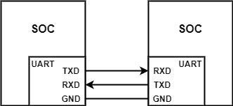
The picture above shows the UART serial port TTL level hardware connection, where:
- TXD: used to send data, should be connected to the RXD pin of the receiving device;
- RXD: used to receive data, should be connected to the TXD pin of the sending device;
- GND: Provides the same reference level for both sides.
UART configuration
In order to use UART for data transmission, you usually need to configure the following parameters:
- Baud rate: the number of bits transmitted per second, usually 9600, 19200, 115200, and other options
- Data bits: There can be 5, 6, 7, or 8 bits of data. Generally, we transmit data in bytes (8 bits), and the sender changes the status of the data line (high level or low level) bit by bit. ) to send them out. When transmitting data, the lowest bit is transmitted first and the highest bit is transmitted last.
- Check bit: used to verify the correctness of data transmission. It can only detect errors but cannot correct them.
- Stop bit: used to indicate that the current data transmission is completed, which is a logic level of “1”
UART timing
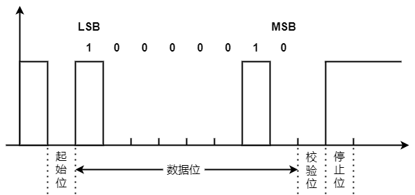
The picture above shows the waveform of ‘A’ (0x41) sent with 8 data bits + 1 even parity bit + 1 stop bit. The binary number of ‘A’ is 01000001. It is transmitted in little endian, that is, the low bit (LSB) is first, and the high bit (MSB) after
- When idle, the data line is high
- Start bit, when data needs to be sent, UART will change the state of TXD to a low level, usually 1bit
- For data bits, the sender changes the status of the data line one by one (high level or low level) and sends them out. First, bit[0] is transmitted, and its value is 1; then bit[1] is sent, and its value is 1. The value is 0, and so on
- Parity bit, even parity: data bit + parity bit The number of bits with a value of “1” is an even number, so the parity bit is a low-level
- Stop bit, because the stop bit is configured as 1bit, so the stop bit is 1bit high-level
UART packet sending channel
The contract delivery channel is as follows:
- The application can call bk_uart_send() to send the packet
- UART hardware package
UART packet receiving channel
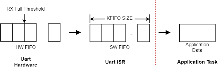
The UART packet receiving channel is shown in the figure above:
- UART interrupt packet reception: When the UART RX or UART RX Finish interrupt occurs, the software enters the UART interrupt processing function. The UART interrupt reads data from the hardware FIFO and puts it into the RX FIFO. If there is an application waiting for data at this time, wake up the application to receive the packet.
- UART application packet reception: When the application calls bk_uart_recv(), data will be read from the UART RX FIFO. When there is no data in the UART RX FIFO, if the timeout is set to 0, bk_uart_recv() will return immediately, otherwise, it will wait until Timeout or new data is received in UART RX FIFO.
UART packet flow control
When the rate at which the UART interrupt fetches packets from the UART HW FIFO is less than the rate at which the UART hardware fills the packets into the HW FIFO, the UART HW FIFO will be Full. If UART hardware flow control is enabled, the UART hardware will notify the sender to stop sending packets, otherwise packet loss will occur.
In the same way, when the rate at which the UART application fetches packets from the SW FIFO is less than the rate at which the UART interrupt fills the SW FIFO with packets, the UART SW FIFO will be Full. When the SW FIFO is Full, the interrupt will read the data in the hardware FIFO and discard it. At this time, the log “rx kfifo is full” will be printed. When this situation occurs, it may affect the application function. Usually, the solution is to improve the application Program processing speed, such as increasing the priority of application tasks, etc.
UART application scenarios
Currently, UART supports three different application methods:
- Use the default UART interrupt processing flow: Use the default bk_uart_send()/bk_uart_recv to process UART transceiver packets. The transceiver packet channel is as described in the UART packet receive channel section. Usually, this method can meet the needs of most applications.
- Use the default UART interrupt processing flow and register the user callback at the same time: Same as the first method, the only difference is that after the UART interrupt is generated, the user-registered callback will be called.
const bk_uart_config_t uart1_config[] =
{
  [0] =
  {
      .baud_rate     = 115200,
      .data_width    = BK_DATA_WIDTH_8BIT,
      .parity  = BK_PARITY_NO,
      .stop_bits = BK_STOP_BITS_1,
      .flow_control = FLOW_CTRL_DISABLED,
      .flags   = 0,
  }
}

char send_buf[4]={0x11,0x22,0x33,0x44};
bk_uart_initialize(UART1_PORT, &uart1_config[0], NULL);  // Initialize serial port
bk_uart_send(UART1_PORT, send_buf, 4);                   // UART write
bk_uart_recv(UART1_PORT, send_buf, 4, 0);                //UART read
Watchdog Timer
Watchdog is actually a hardware timer, and the timer expiration will trigger the system watchdog to restart.
- bk_wdg_initialize(timeout_ms) can set the watchdog timer time. The current time configuration range is (1~0xFFFF).
- bk_wdg_reload() resets the watchdog timer.
How to use Watchdog
There are two common ways to use watchdog:
- Feeding the dog during periodic interrupts, such as feeding the dog during the OS tick interrupt. When the tick interrupt fails to feed the dog in time due to software problems, such as the shutdown interrupt being too long, the watchdog times out and eventually triggers a watchdog restart. In this way, abnormal software interruption problems can be discovered in time. This type of watchdog usage is often called an interrupt watchdog.
- Feed the dog in a periodic task, such as feeding the dog in an idle task. Usually the idle task is the task with the lowest priority in the entire system. When there is a problem with the software, such as a task that appears in an infinite loop and occupies the CPU for a long time, the idle task cannot be scheduled. , resulting in failure to feed the dog in time, eventually triggering the watchdog to restart. In this way, problems in software task scheduling can be discovered in time. This type of watchdog use is often called a task watchdog.
Interrupt Watchdog
In BK7238, Interrupt Watchdog is enabled by default, and the timeout can be set through the CFG_INT_WDG_ENABLED switch in sys_config_bk7238.h. Generally, applications should not turn off interrupt watchdog and CFG_INT_WDG_PERIOD_MS. .
When the application needs to implement the interrupt watchdog entirely by itself, please use the CFG_INT_WDG_ENABLED macro to turn off the system’s default interrupt watchdog.
Task Watchdog
Task Watchdog is also implemented in BK7238, but it is not based on real hardware Watchdog. The timeout can be set through the CFG_TASK_WDG_ENABLED switch and CFG_TASK_WDG_PERIOD_MS in sys_config_bk7238.h. The specific implementation is as follows:
The global variable s_last_task_wdt_feed_tick represents the last dog feeding time. Update s_last_task_wdt_feed_tick in the idle task. In the tick interrupt, it is judged whether the last dog feeding time exceeds the task watchdog timeout. If it times out, a task watchdog timeout warning message will be displayed, but the system will not be restarted.
I2C
I2C is a serial synchronous half-duplex communication protocol that requires only two buses, namely the serial data line (SDA) and the serial clock line (SCL). These lines require pull-up resistors. BK7238 is embedded with I2C interface and can be used as master mode or slave mode. It supports standard (up to 100 kbps) as well as fast (up to 400 kbps) modes with 7-bit addressing.
I2C is simple and cheap to manufacture and is primarily used for short-range communication (within one foot) of low-speed peripheral devices.

The picture above shows the I2C hardware connection, where:
- SCL: Clock signal, provides a clock for data transmission and is used to synchronize data transmission;
- SDA: used to transmit data.
#define I2C_TEST_EEPROM_LEGNTH          8

#if CFG_USE_I2C1
static void i2c1_test_eeprom(char *pcWriteBuffer, int xWriteBufferLen, int argc, char **argv)
{

    int i;
    DD_HANDLE i2c_hdl;
    unsigned int status;
    unsigned int oflag;
    I2C_OP_ST i2c1_op;
    I2C1_MSG_ST i2c_msg_config;

    os_printf(" i2c1_test_eeprom start  \r\n");

    i2c_msg_config.pData = (UINT8 *)os_malloc(I2C_TEST_EEPROM_LEGNTH);
    if (i2c_msg_config.pData == NULL) {
        os_printf("malloc fail\r\n");
        goto exit;
    }

    oflag   = (0 & (~I2C1_MSG_WORK_MODE_MS_BIT)     // master
               & (~I2C1_MSG_WORK_MODE_AL_BIT))    // 7bit address
              | (I2C1_MSG_WORK_MODE_IA_BIT);     // with inner address

    i2c_hdl = ddev_open(I2C1_DEV_NAME, &status, oflag);

    if (os_strcmp(argv[1], "write_eeprom") == 0) {
        os_printf("eeprom write\r\n");

        for (i = 0; i < I2C_TEST_EEPROM_LEGNTH; i++)
            i2c_msg_config.pData[i] = (i << 2) + 0x10 ;

        i2c1_op.op_addr    = 0x08;
        i2c1_op.salve_id   = 0x50;      //send slave address
        i2c1_op.slave_addr = 0x73;      //slave: as slave address

        do {
            status = ddev_write(i2c_hdl, (char *)i2c_msg_config.pData, I2C_TEST_EEPROM_LEGNTH, (unsigned long)&i2c1_op);
        } while (status != 0);
    }
    if (os_strcmp(argv[1], "read_eeprom") == 0) {
        os_printf("eeprom read\r\n");

        i2c1_op.op_addr    = 0x08;
        i2c1_op.salve_id   = 0x50;      //send slave address
        i2c1_op.slave_addr = 0x73;      //slave: as slave address

        do {
            status = ddev_read(i2c_hdl, (char *)i2c_msg_config.pData, I2C_TEST_EEPROM_LEGNTH, (unsigned long)&i2c1_op);
        } while (status != 0);
    }

    for (i = 0; i < I2C_TEST_EEPROM_LEGNTH; i++)
        os_printf("pData[%d]=0x%x\r\n", i, i2c_msg_config.pData[i]);

    ddev_close(i2c_hdl);

    os_printf(" i2c2 test over\r\n");

exit:

    if (NULL != i2c_msg_config.pData) {
        os_free(i2c_msg_config.pData);
        i2c_msg_config.pData = NULL;
    }
}
Now you can purchase the BK7238 modules from here